-
Foreword
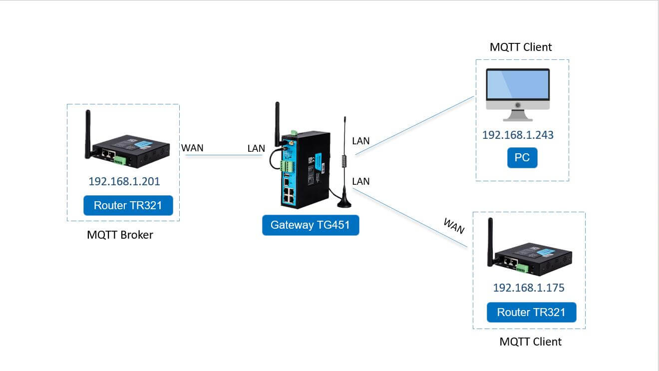
In this case, we will need 2pcs TR321 and a PC, one of it works as MQTT Broker, another TR321 and PC works as MQTT Client. All of these devices connected with the same LAN of gateway.
-
MQTT Broker Settings
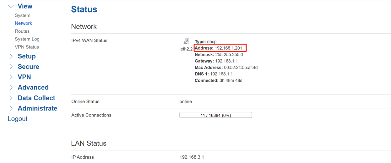
- (1) Open the WEBUI of MQTT Broker router, check the network status, the WAN IP will be the MQTT Broker address.
- (2) Enable MQTT Broker feature at the Data Collect, then Save&Apply.

-
MQTT Client Settings
-
(1) Network status of Client router

-
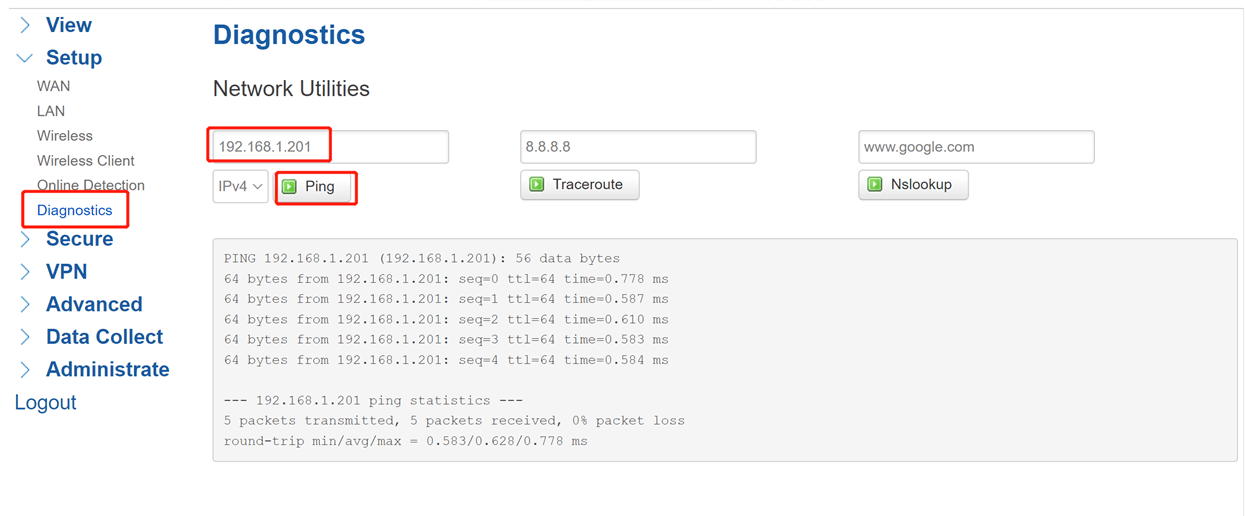
(2) Diagnostics
Come to Setup-Diagnostics, we can check communication between MQTT Broker router and Client router here.
-
(3) Data Collect
Now setup data collection at the Data Collect part. Enable data collect then set collect and report period.
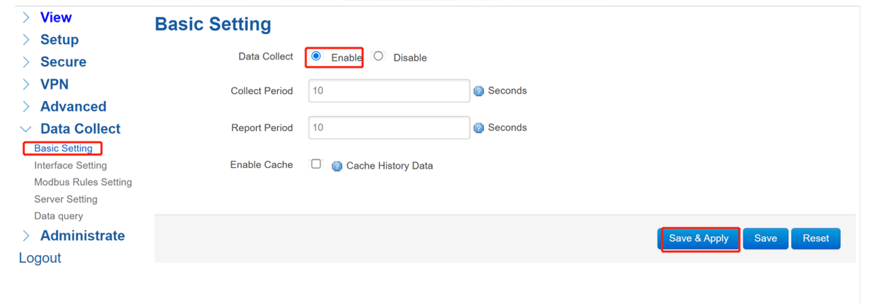
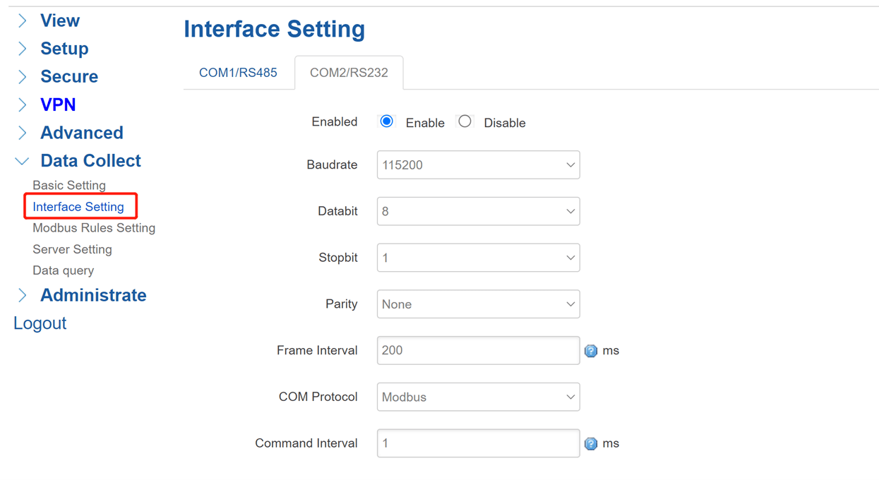
Setup the corresponding interface parameters of slave device.
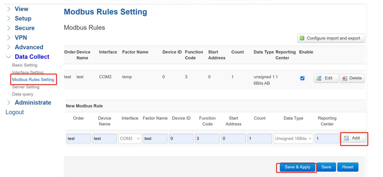
If using Modbus devices, need to setup Modbus Rules.
-
(4) Server Settings
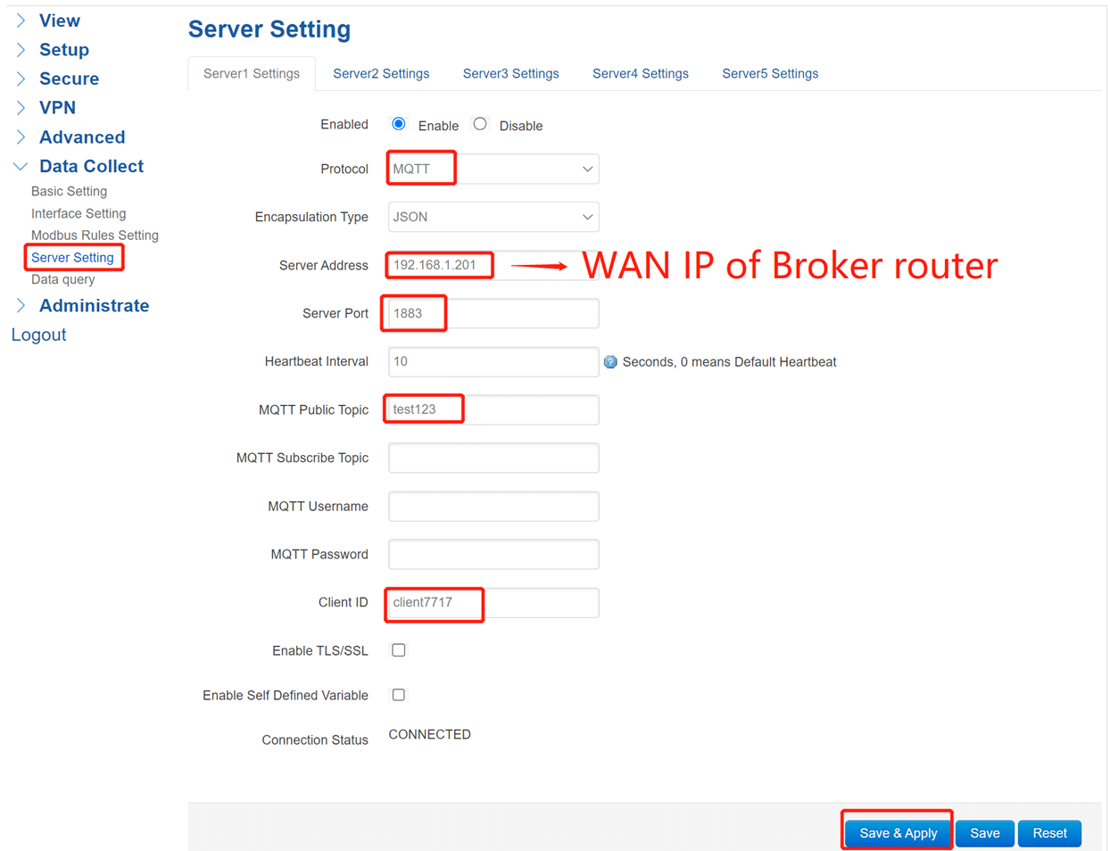
Chose the server protocol as Modbus, server address will be the WAN IP of MQTT Broker router, port is 1883, then set the public topic as you wish and setup a unique client ID. After click Save&Apply, you can see the connection status changes to CONNECTED.
-
(5) Modbus Slave Setting
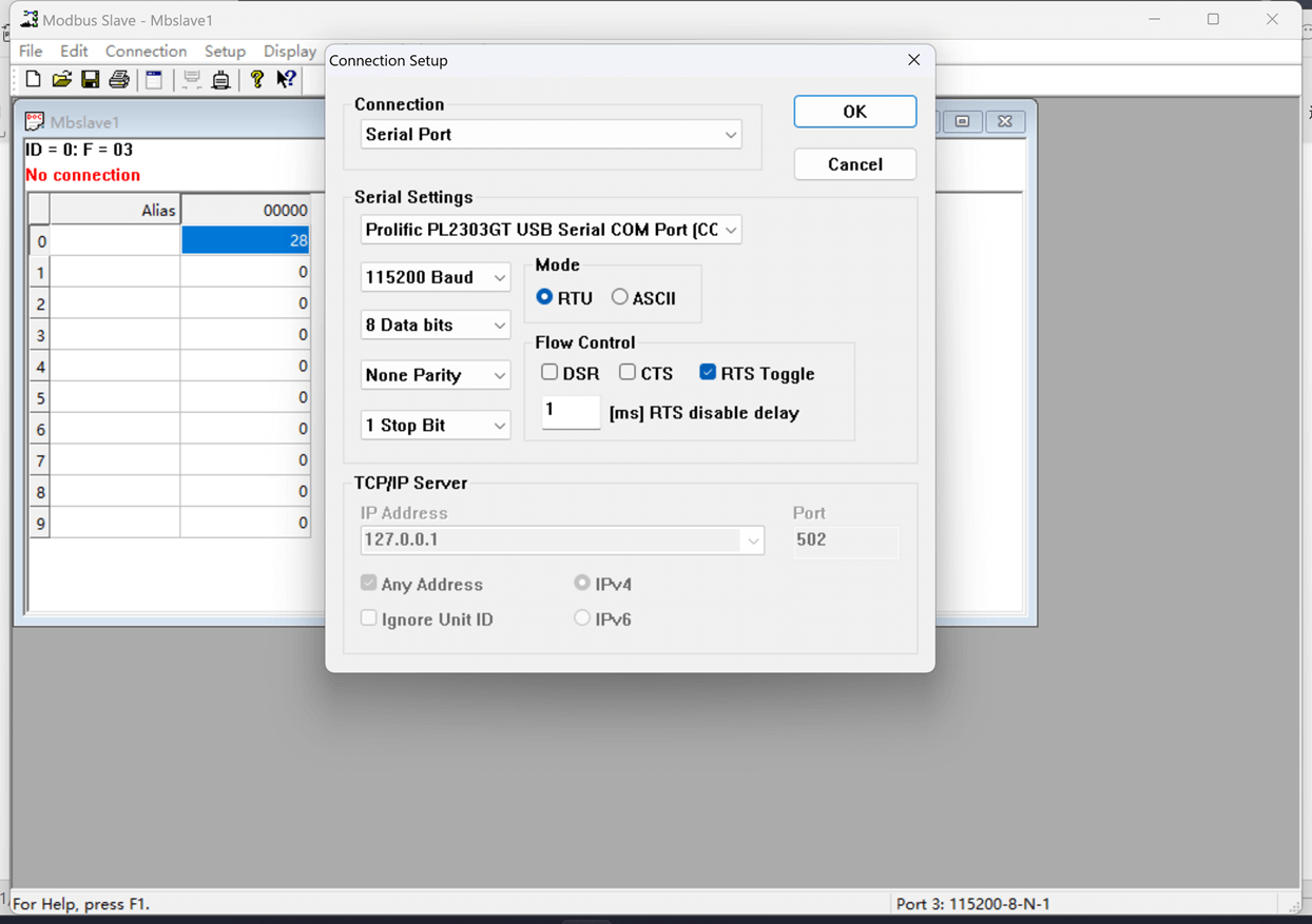
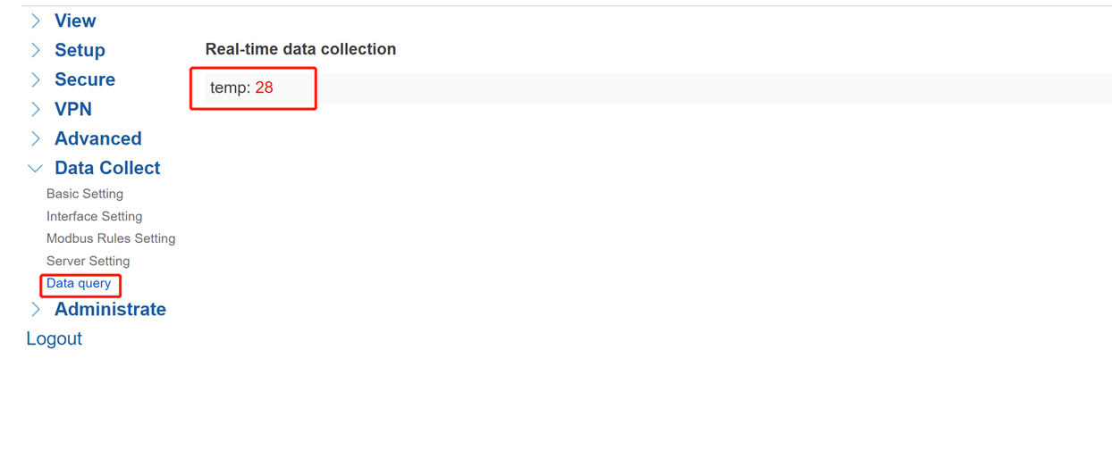
Here we use Modbus Slave to simulate slave device, setup the corresponding interface parameters of Client router then click connect. In this case, we set the value as 28, the data also can be checked at WEBUI.
-
(6) MQTT.fx Settings
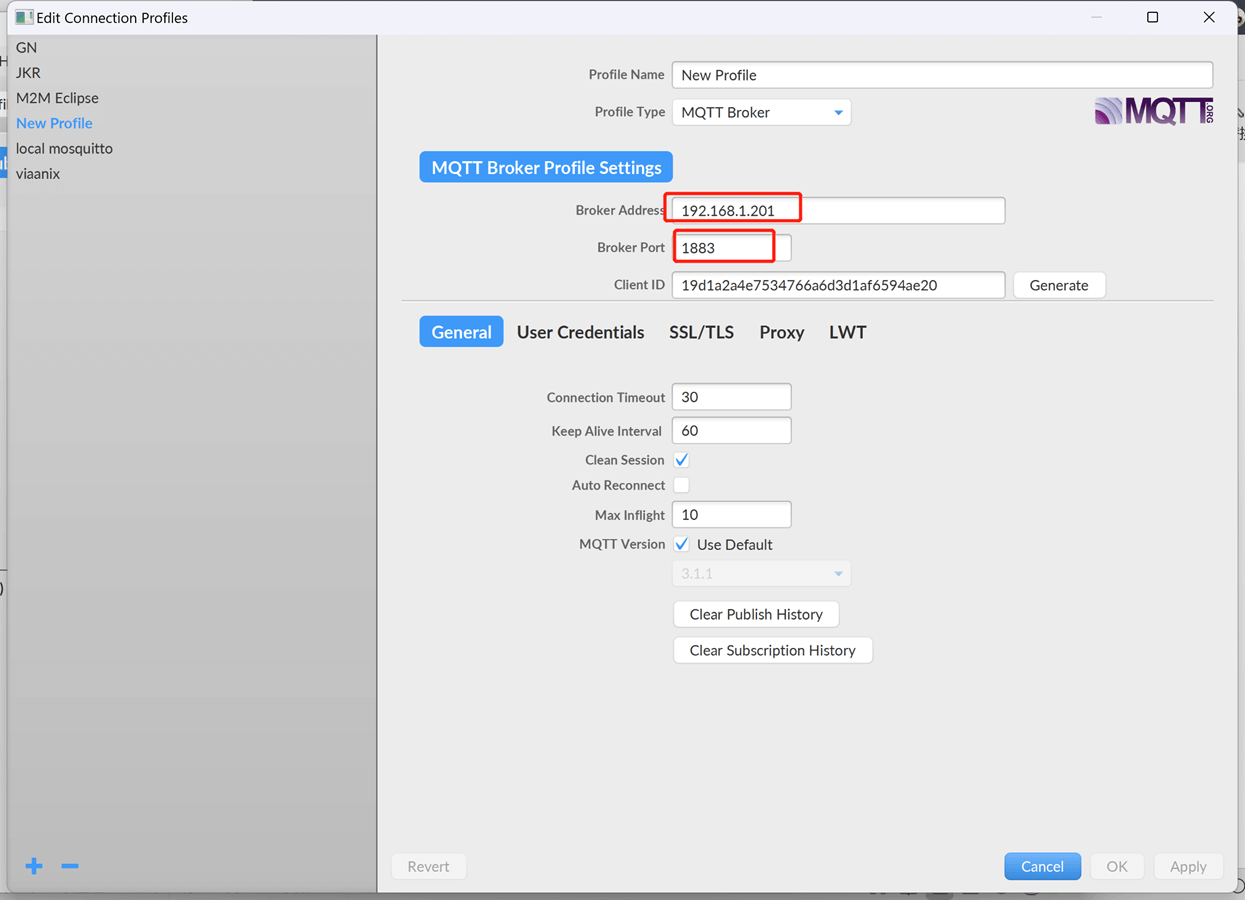
Open MQTT.fx or other software to works as MQTT client at PC, the Broker Address should be the WAN IP of Broker router, and Broker port will be 1883, click Connect after setup.
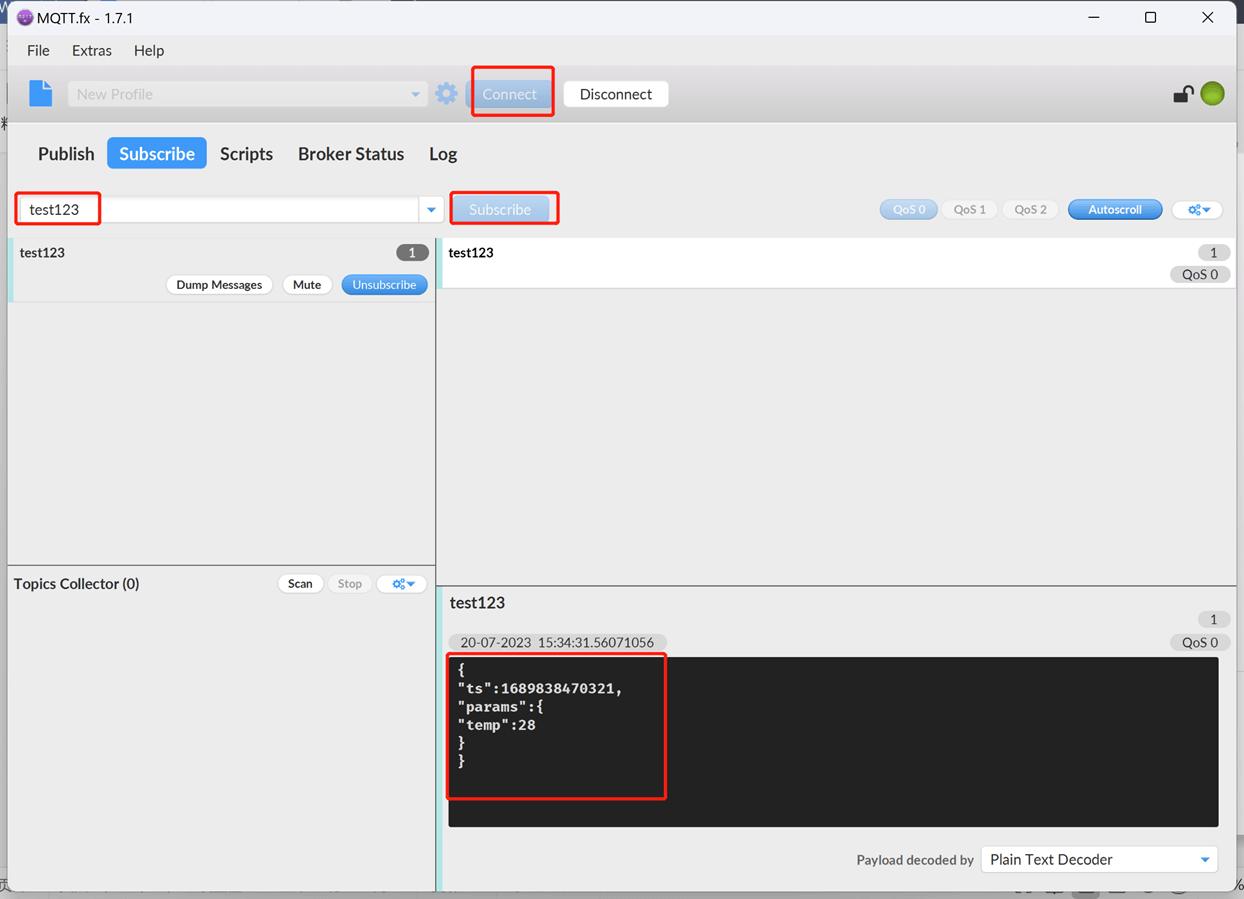
Then subscribe to the public topic which Client router set, here we set is as test123. We will receive the topic message from MQTT Client router.
Relevant MQTT Video: https://www.youtube.com/watch?v=qPBpjeokEwU


2 Comments