How to setup an OpenVPN environment on Bivocom IoT Router&Gateway?
This article will explain in detail the entire process from setting up the OpenVPN environment, configuring the device, and then connecting the network based on three network topologies.
Before configuring the router, you need to confirm which type of network the router is using, wired or SIM card. It’s the best way to configure the server and client WAN with static IP, because DHCP IP changes from time to time. In this case, the OpenVPN server and client are both configured as public SIM card with static IP.
Network Topology 1
In this case, we’re going to setup an OpenVPN environment for remote encrypted communication and access. There is a router TR321 works as OpenVPN server, another TR321 works as OpenVPN client. And the two routers both connect with a PC. After the VPN tunnel is established, the two hosts can communicate and access each other.

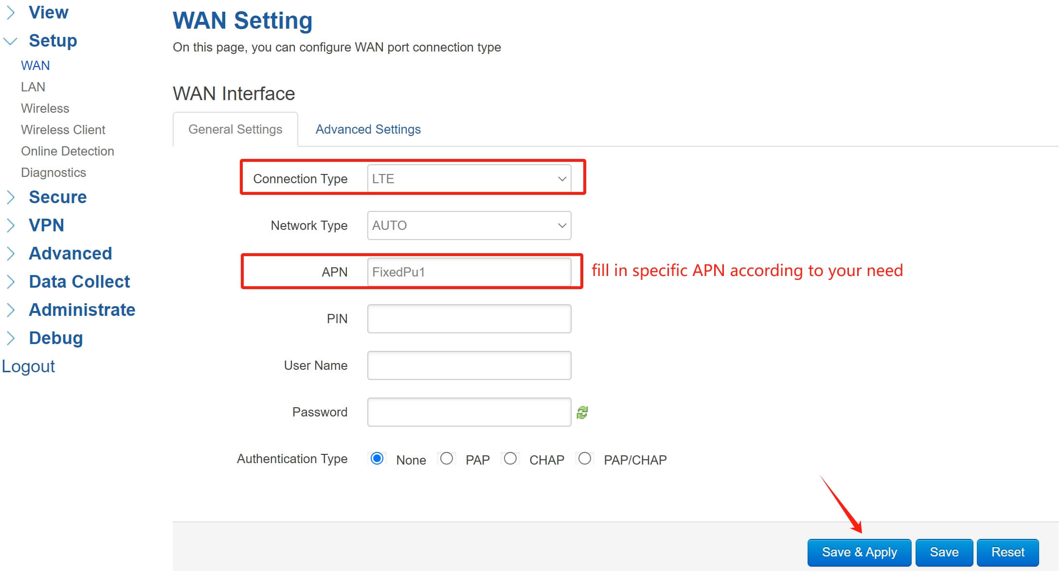
1.WAN Configuration
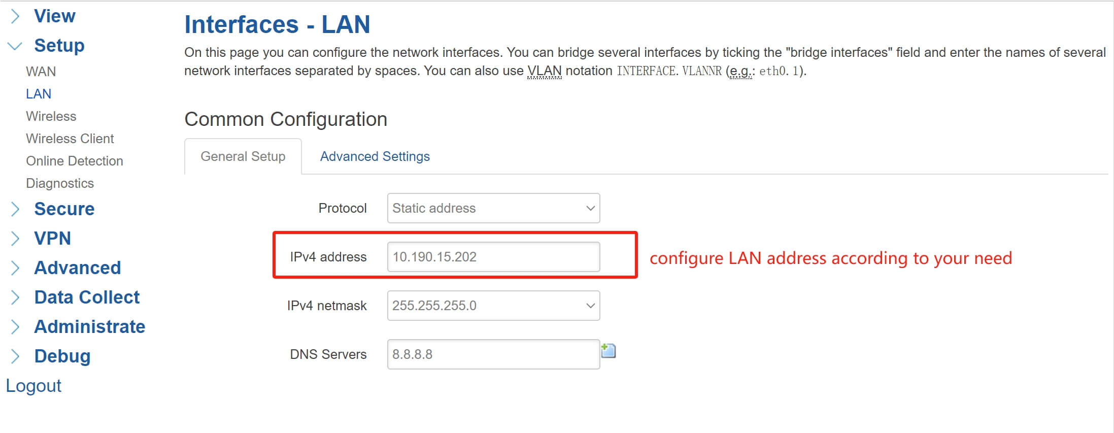
2.LAN Configuration
3.OpenVPN Server Configuration
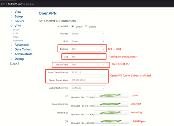
Select Protocol as TCP or UDP, set a unique port, the Device Type must be TAP, the OpenVPN Tunnel Subnet and Mask can set as you wish, but the tunnel subnet must distinguish with other VPN subnet. Upload the ca.crt, server.crt, server.key and dh files to the server.
Leave the Peer Subnet Address and Mask empty, so that multiple clients can connect to the server. Enable NAT feature. Configure the Extra option, add a route rule, so that the server router can access the client router downward. The rule format should be like:
“route 192.168.100.0 (client LAN network segment) 255.255.255.0 (client netmask) 100.100.100.10 (client tunnel IP)”
Ex: “route 10.190.1.0 255.255.255.0 11.11.11.2”
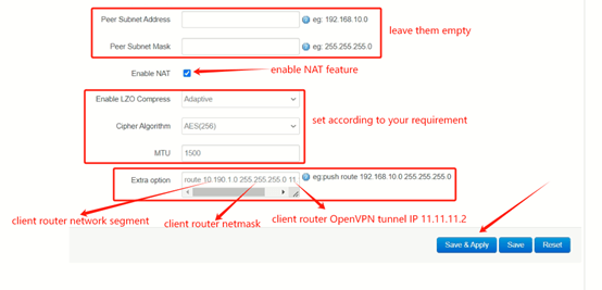
In this case, there is only one client connect to the server. If you have multiple clients that need to connect to the server, you have to add corresponding rules for different clients. After setup, click Save&Apply.
4.OpenVPN Client Configuration
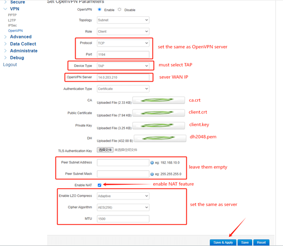
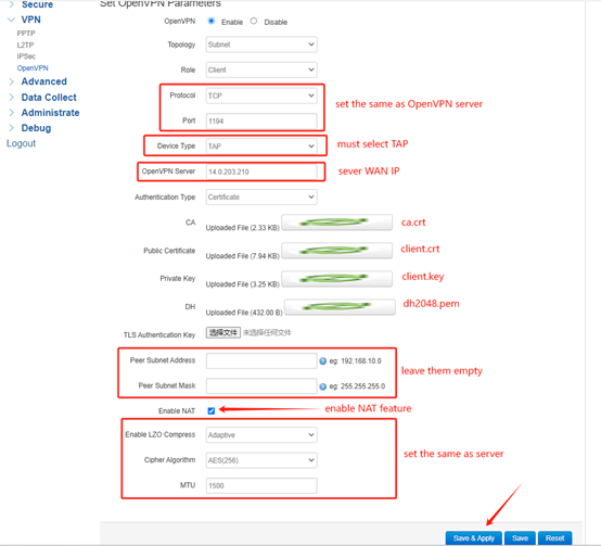
Set Protocol and Port the same as server. Device Type select TAP. Set OpenVPN Server as Server WAN IP. Upload the ca.crt, client.crt client.key and dh files to the client. Leave the Peer Subnet Address and Mask empty. Enable NAT feature. The LZO Compress, Cipher Algorithm and MTU should set the same as server. After setup, click Save&Apply.
5.Test Result

The two PC hosts can ping and communicate with each other.
Network Topology 2
Compare with topology 1, there are multiple client routers connect to the server router.Each client router is connected to a machine. After the VPN tunnel is established, every machine can communicate and access each other.
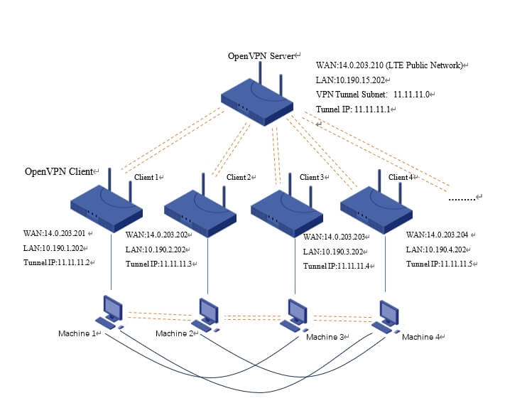
1.WAN Configuration

2.LAN Configuration

3.OpenVPN Server Configuration
Select Protocol as TCP or UDP, set a unique port, the Device Type must be TAP, the OpenVPN Tunnel Subnet and Mask can set as you wish, but the tunnel subnet must distinguish with other VPN subnet. Upload the ca.crt, server.crt, server.key and dh files to the server.
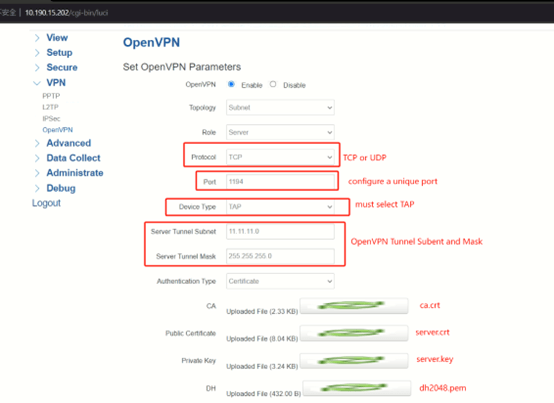
Leave the Peer Subnet Address and Mask empty, so that multiple clients can connect to the server. Enable NAT feature. In this case, there are many clients connect with the server, if you want every client to be able to communicate with each other, you need to configure the Extra option. Add route rule for different clients, the rule format should be like:
“push route 192.168.100.0 (client LAN network segment) 255.255.255.0 (client netmask) 100.100.100.10 (client tunnel IP)”.
Ex: push route 10.190.1.0 255.255.255.0 11.11.11.2
push route 10.190.2.0 255.255.255.0 11.11.11.3
push route 10.190.3.0 255.255.255.0 11.11.11.4
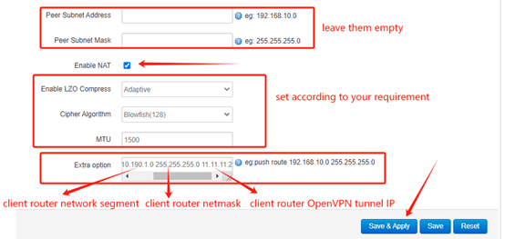
After setup, click Save&Apply.
4.OpenVPN Client Configuration
Set Protocol and Port the same as server. Device Type select TAP. Set OpenVPN Server as Server WAN IP. Upload the ca.crt, client.crt client.key and dh files to the client. Leave the Peer Subnet Address and Mask empty. Enable NAT feature. The LZO Compress, Cipher Algorithm and MTU should set the same as server. After setup, click Save&Apply.
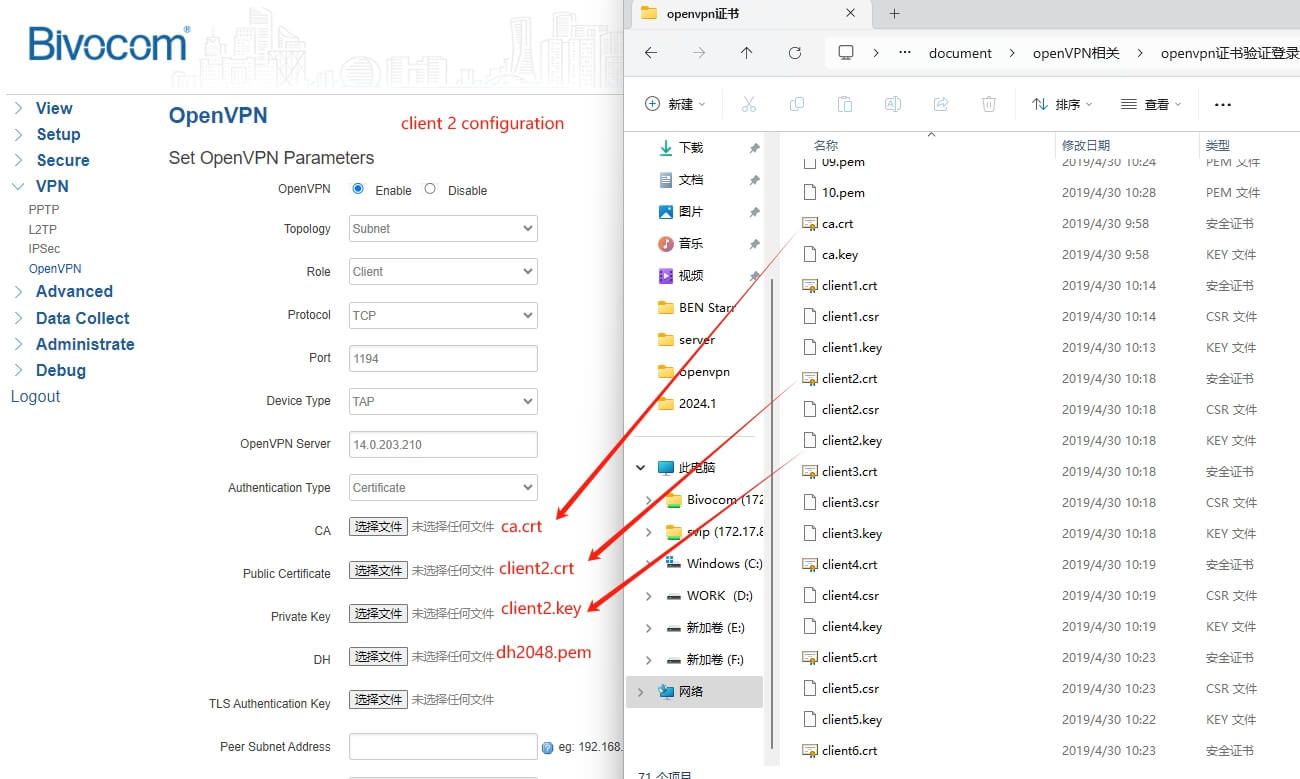
NOTE: The ca and dh file can be used both server and client, but the client.crt and client.key should be distinguished. Each client should be configured with a unique crt and key file.
Network Topology 3
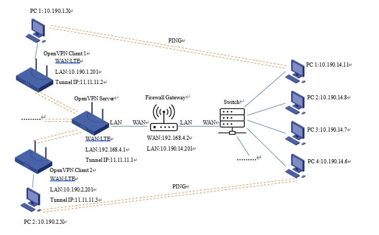
In this network topology, there is an extra firewall gateway connected to the OpenVPN server, and the gateway is connected to a switch that connects with multiple PC clients.
The PC clients on both sides need to communicate with each other through OpenVPN tunnel.
1.OpenVPN Server Configuration
(1) Select Protocol as TCP or UDP, set a unique port, the Device Type must be TAP, the OpenVPN Tunnel Subnet and Mask can set as you wish, but the tunnel subnet must distinguish with other VPN subnet. Upload the ca.crt, server.crt, server.key and dh files to the server.
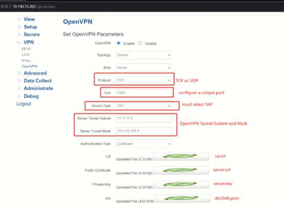
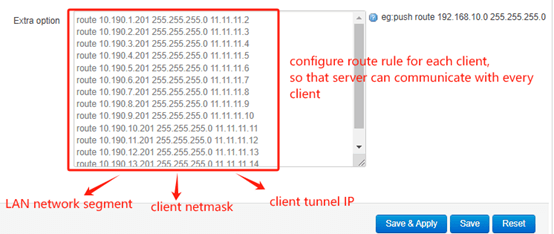
Leave the Peer Subnet Address and Mask empty, so that multiple clients can connect to the server. Enable NAT feature. In this case, there are many clients connect with the server, if you want every client to be able to communicate with each other, you need to configure the Extra option. Add route rule for different clients, the rule format should be like:
“ route 192.168.100.0 (client LAN network segment) 255.255.255.0 (client netmask) 100.100.100.10 (client tunnel IP)”.
Ex: route 10.190.1.0 255.255.255.0 11.11.11.2
route 10.190.2.0 255.255.255.0 11.11.11.3
route 10.190.3.0 255.255.255.0 11.11.11.4
In order to enable the PC host in network segment 10.190.14.X to access the OpenVPN server and the client behind the server through the firewall, you need to add one more route rule: “push route 10.190.14.0 255.255.255.0 11.11.11.1”.
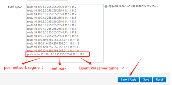
After set up the extra option, click Save&Apply.
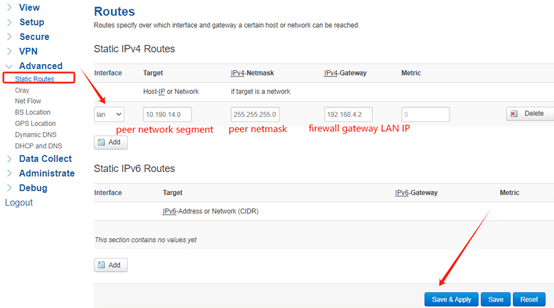
(2) In order to make network communication between clients on both sides, you need to configure static route and modify the firewall rules of OpenVPN Server.
Add a static route so that the server can point to the 10.190.14.0 segment, the gateway IP should be the firewall WAN IP.
Modify the firewall custom rule, add a SNAT rule so that the data packet cam pass through the firewall of OpenVPN server to reach the destination address. The command should be:
“iptables -t nat -A POSTROUTING -s 11.11.11.0/255.255.255.0 -o br-lan -j SNAT –to-source 192.168.4.1”.
#11.11.11.0 OpenVPN server tunnel segment 255.255.255.0 netmask 192.168.4.1 OpenVPN server LAN IP
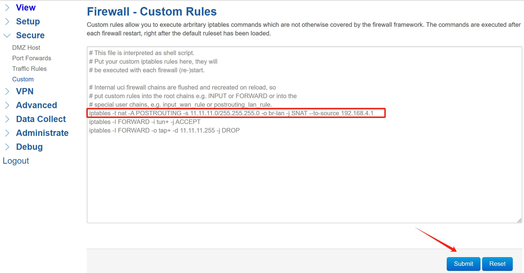
After configure, click Submit, then restart the firewall or reboot the device.
2.OpenVPN Client Configuration
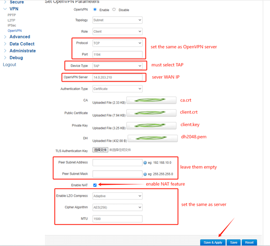
Set Protocol and Port the same as server. Device Type select TAP. Set OpenVPN Server as Server WAN IP. Upload the ca.crt, client.crt client.key and dh files to the client. Leave the Peer Subnet Address and Mask empty. Enable NAT feature. The LZO Compress, Cipher Algorithm and MTU should set the same as server. After setup, click Save&Apply.
3.Fixed Tunnel IP Configuration
If you want to fix the tunnel IP of each OpenVPN client, you need to do some extra configurations.
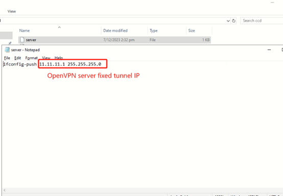
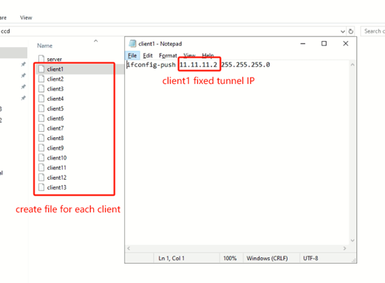
(1) Create a folder named “ccd”, this folder is used to store the fixed tunnel IP of each OpenVPN client. Then create file for every client, the file content should be “ifconfig-push 10.10.10.2 (fixed tunnel IP) 255.255.255.0 (netmask)”.
Ex: Client1: ifconfig-push 11.11.11.2 255.255.255.0
Client2: ifconfig-push 11.11.11.3 255.255.255.0
Client3: ifconfig push 11.11.11.4 255.255.255.0
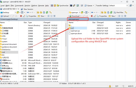
(2) Upload the ccd folder to the directory “/etc/openvpn/” of the OpenVPN server.
(3) Add another extra option in OpenVPN server configuration: “client-config-dir /etc/openvpn/ccd”, when the OpenVPN tunnel is established, the server will read the ccd file in the system directory. Then the server will assigns a fixed tunnel IP for each client based on the contents of the file.
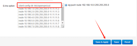
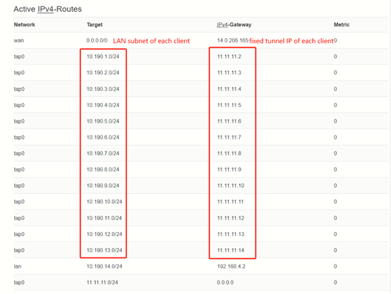
After setup, Click Save&Apply, then you can check the fixed IP of each client in the Routes page.


Comment