How IoT Gateway Helps to Monitor ECU of Automobile Remotely
With the increasing popularity of new energy vehicles, ensuring their safety remains a crucial mission for automobile manufacturers.
Among the thousands of parts in vehicles, ECU(Electronic Control Unit) plays a vital role in enhancing vehicle performance, improving safety features, and optimizing fuel efficiency. They serve as the brains behind many aspects of modern automotive systems. While, the most commonly used method of ECU diagnosis is through CAN or CAN FD data.
A 5G/4G IoT gateway can assist engineers in remotely collecting CAN/CANFD data from ECUs, thereby significantly enhancing the efficiency of car diagnosis. This article provides an outline of how Bivocom helps monitor Automobile ECUs.
What is ECU?
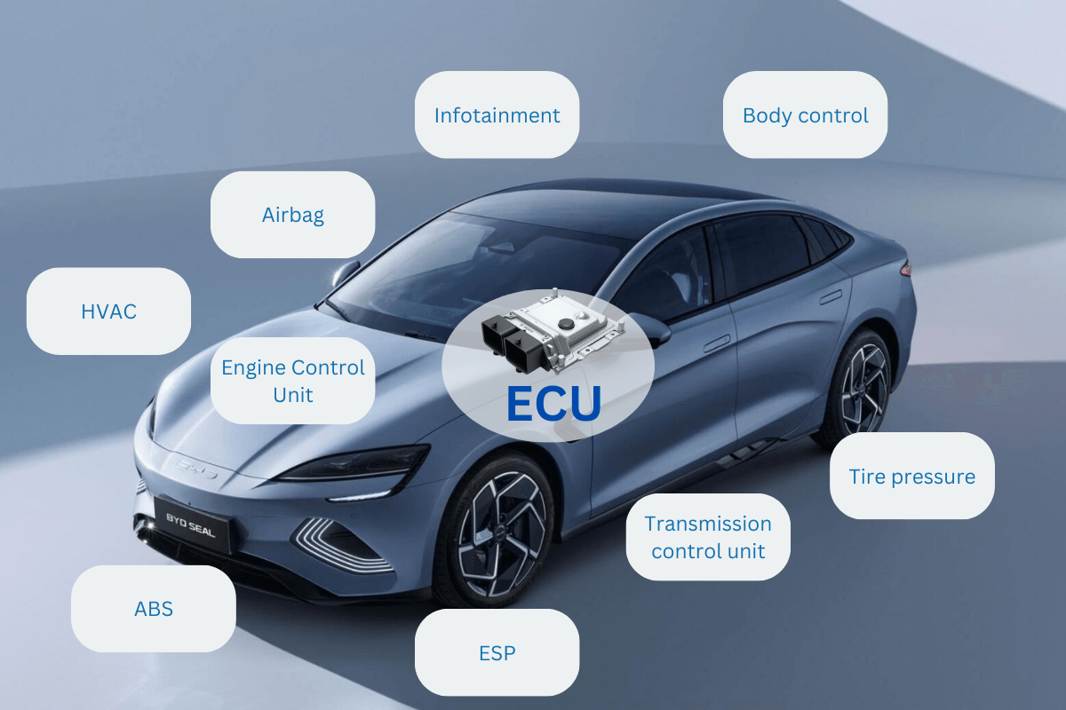
The Electronic Control Unit (ECU) of a vehicle is a specialized computer that controls and manages the electronic systems within the vehicle. It is often referred to as the “vehicle’s brain.”
In an automobile, the main function of the ECU is to monitor and regulate numerous systems and subsystems to ensure proper operation and optimal performance. Some of the key functions of the vehicle ECU include:
1. Engine Management: The ECU controls various aspects of the engine, such as fuel injection timing, ignition timing, air-fuel mixture ratios, and idle speed. It receives input from engine sensors and makes adjustments accordingly.
2. Transmission Control: The ECU manages the shifting of gears in automatic transmissions, optimizing gear changes for smooth acceleration, fuel efficiency, and overall performance.
3. Anti-lock Braking System (ABS): The ECU monitors the wheel speed sensors and controls the braking system to prevent wheel lock-up during sudden braking, enhancing vehicle control and safety.
4. Stability Control: The ECU utilizes sensors to detect factors such as vehicle speed, steering angle, and yaw rate to provide stability control. It can selectively apply brakes or adjust engine power to help prevent skidding or loss of control.
5. Airbag System: The ECU is responsible for monitoring crash sensors and deploying airbags in the event of a collision, contributing to occupant safety.
6. Climate Control: In vehicles equipped with electronic climate control systems, the ECU manages the temperature, fan speed, and distribution of air to maintain desired cabin conditions.
What is CAN FD and CAN?
CAN FD stands for Controller Area Network Flexible Data Rate, while CAN stands for Controller Area Network. Both terms refer to a communication protocol used in automotive and industrial applications for real-time data exchange between electronic control units (ECUs).
CAN is a widely adopted protocol that enables communication between different components in a vehicle, such as the engine control unit, transmission control unit, body control module, and more. It allows for reliable and efficient data transmission, with a focus on robustness and fault tolerance.
CAN FD is an enhanced version of the CAN protocol that provides higher data rates and increased payload size. It allows for faster communication and the transfer of larger amounts of data between ECUs. This increased bandwidth is particularly useful in modern vehicles with multiple ECUs that need to exchange a significant amount of data, such as in advanced driver-assistance systems (ADAS) and infotainment systems.
Overall, while CAN is the traditional protocol used for communication in automotive and industrial applications, CAN FD offers improved capabilities for faster and more efficient data exchange in advanced systems.
What is IoT Gateway?
An IoT (Internet of Things) gateway is a device component that serves as a bridge or intermediary between IoT devices and the cloud or network infrastructure. It acts as a communication hub, collecting data from multiple IoT devices, performing data processing and filtering, and transmitting the data to a central server or cloud platform for further analysis and action.
The primary functions of an IoT gateway include:
- Device connectivity: The gateway enables connectivity with various IoT devices using different communication protocols such as Wi-Fi, cellular, or wired It serves as a universal translator, allowing devices with different protocols to communicate seamlessly.
- Data aggregation: The gateway collects data from connected IoT devices and sensors. It can consolidate data from multiple sources into a unified stream, ensuring that all relevant data is transmitted efficiently.
- Data preprocessing: The gateway performs data preprocessing tasks such as data filtering, compression, encryption, or format conversion. This helps in reducing network bandwidth usage, optimizing data transmission, enhancing data security, and preparing the data for further analysis.
- Local computing and decision-making: In some cases, an IoT gateway may have computing capabilities to perform local processing and decision-making tasks. This is particularly useful in situations where real-time or near-real-time response is required, as it reduces latency by processing data locally.
- Security and device management: The gateway often includes security features to authenticate and authorize devices, encrypt data transmission, and protect against unauthorized access. It may also provide device management functionalities such as firmware updates, configuration management, and remote monitoring.
By serving as a central point for connectivity, data management, and security, IoT gateways help streamline and optimize the flow of data between IoT devices and the cloud or network infrastructure, enabling effective implementation of IoT solutions.
How IoT Gateway to Acquire Data from ECU?
Bivocom IoT Gateway allows engineers to collect CAN/CAN FD data from ECU and log the data to a file, which can help to analyze or diagnose the state of the car, including the Anti-lock Braking System, chassis, engine, etc. The following steps will tell you how to configure Bivocom to communicate with ECUs. In this case, I will use a Vector CANalyzer(VN1630) to simulate an ECU and analyze data.
- Setup the same parameters of IoT Gateway and Vector
- Connect IoT Gateway and Vector with the right port.
- Login to the CMD interface of Bivocom(telnet/SSH), and then send the commands to setup CAN FD parameters. CAN FD can compatible with CAN and CANFD. Here we set the bitrate as 500K, dbitrate 2000K, sample point set 80%, dsample point will be 70%.
ip link set can0 down
ip link set can0 type can bitrate 500000 sample-point 0.8 dbitrate 2000000 dsample-point 0.70 fd on
ip link set can0 up
ip -details link show can0

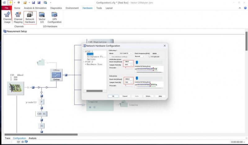
- Open Vector CANalyzer, then setup the corresponding settings:
-Hardware -> Network Hardware -> Setup
- Arbitration phase: Change the Baud rate into “500K”, Sample point “80%”
- Data phase: Baud rate into “2000K”, Sample point “70%”
- Press OK button
- Click start button
- Receive and Send CAN/CAN FD frame data
- Bivocom IoT Gateway settings&commands
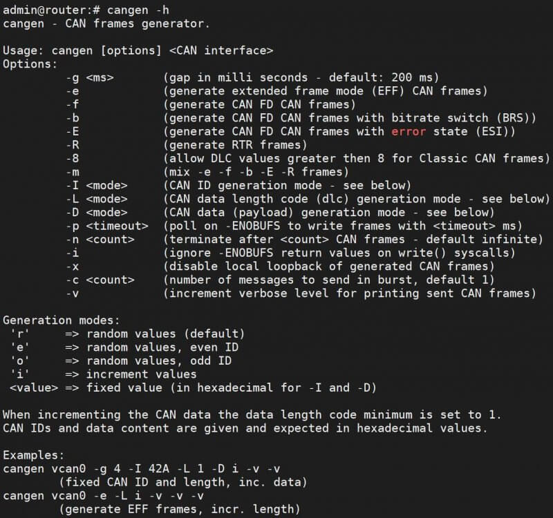
- Send CAN/CAN FD frame data: Use command “cangen -h”to check what we can set to Send CAN/CAN FD data
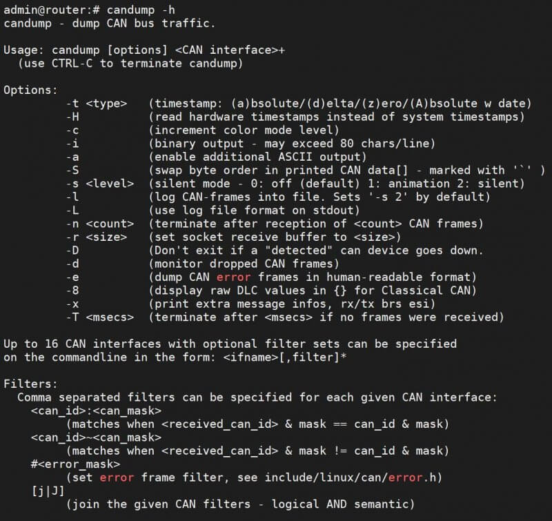
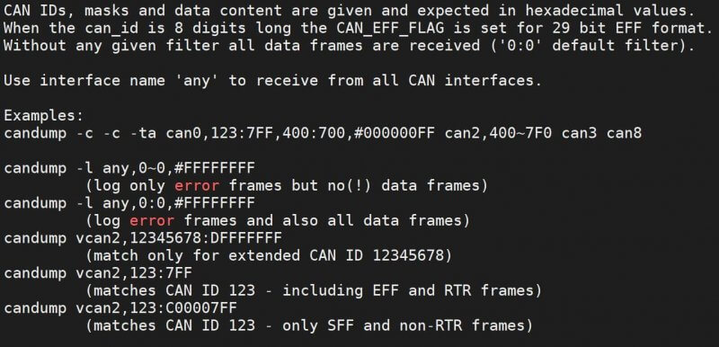
- Receive CAN/CAN FD frame data: Use command “candump -h”to check what we can do to receive CAN/CAN FD frame data.
- Vector CANalyzer settings
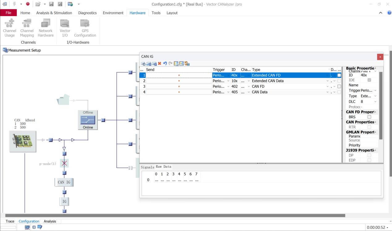
- Insert “CAN IG”function at Configuration
- Right click to add CAN, CAN FD, Extended CAN, Extended CAN FD frame data
- Set the Trigger as Periodic(5ms), and click Send button
After these settings, Vector CANalyzer will start sending multiple mixed CAN/CAN FD data, which data generated by the ECU in the actual vehicle is simulated.
- Communication Example
- Using Bivocom IoT Gateway to Send CAN FD with 2 bits rolling counter frame every 2 ms.
cangen can0 -x -f -D i -L 8 -I 8 -g 2 -n 1000000

- Receive CAN/CAN FD frame data (count 10000 frames)and log the data to a file.
candump can0 -l -n 100000

- Open Logfile to check the data

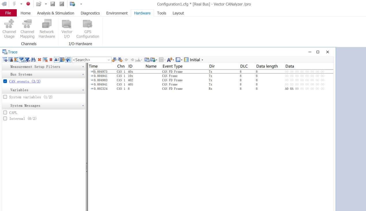
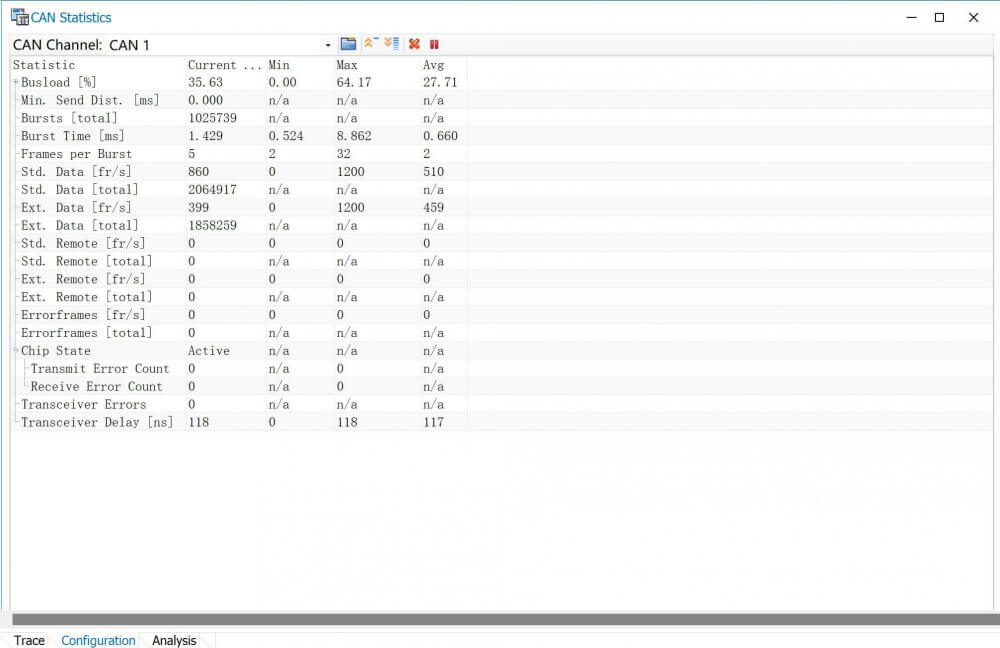
- Check CAN/CAN FD data communication at Vector CANalyzer

1 Comment